What is UML stand for?
UML stands for
U - Unified
M - Modeling
L – Language
What is UML means?
• UML is a visual language that let you model software and process
• UML is made up of notation and diagrams
What is UML definition?
The Unified Modeling Language (UML) is an idea of modeling language in the software field.
UML is initial footstep in developing an object-oriented design methodology.
The Unified Modeling Language (UML) has appeared as admired and efficient means of conceptualizing complex software design challenges and architecting solutions.
In Unified Modeling Language (UML), an "actor" is any agent that interacts with the target system, such as humans or even other computer systems, databases, etc. In the case of humans, a user can take on different actor roles depending on what his or her goal is at any given moment for interacting with the web site.
What is UML?
Unified Modeling language (UML) is a standardized modeling language allowing developers to specify, visualize, construct and document artifacts of as software system. Unified Modeling Language (UML) is an important aspect involved in object oriented software development. It uses graphic notation to create visual models of software systems.
How many Types of Unified Modeling Language (UML) Diagrams?
There are main four different types of Unified Modeling Language (UML) diagrams.
There are total 14 UML diagram types.
UML Diagram:
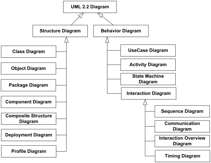
Main different types of UML Diagrams are
- Context Diagram
- Use Case Diagram
- Activity Diagram
- Sequence Diagram
1. Context Diagram
Context Diagram is a high level diagram that represents the actors outside a system that could interact with that system. This diagram is the highest level view of a system. It is similar to block diagram.
Context Diagram shows system as a whole and its inputs and outputs from / to actors.
2. Use Case Diagram
Use Case Diagram are created to visualize the relationship between Actors and Use Cases.
3. Activity Diagram
Activity Diagram is used to display the sequence of activities.
Activity Diagram shows the workflow from start point to the finish point detailing the many decision point.
They may be used to detail situation where parallel processing may occur in the execution of some activities.
4. Sequence Diagram
The graphical representation of the interactions between actors. System and system components during execution of a use case or business process. The model illustrates both what is being exchanged and when the interaction occurs.
No comments:
Post a Comment